4.6.2.1 General
a) Any discharge into the sea of oil or oily mixtures from the ship is prohibited except under the conditions as specified in Annex I of MARPOL. The overboard discharge of any oil, or water containing oil other than from operational OWS into sea, except in extreme emergency for safety of life and/or vessel IS NOT PERMITTED. It is strictly prohibited for any ship’s staff to bypass the Oily Water Separator.
b) The Chief engineer shall ensure to minimize the quantity of water and oil entering the engine room bilge. Regular inspection and maintenance of oil pipes, couplings, and gaskets should be carried out. Additionally, he may:
- Designate personnel required to operate bilge water processing equipment.
- Require vessels to report company when the OWS or any piece of equipment associated with the OWS system is non-operational.
c) A copy of the Bilge Pipeline Diagram shall be posted near the bilge pump.
d) Any oil residues (sludge) must be retained on board for incineration or discharge to the reception facility.
e) Wilden Pump to be kept in any storage box / locker or any other locking arrangement in the ER with Keys to be in master’s custody.
f) When Wilden Pump needs to be used in Engine Room, the Master will obtain company's (Tech Superintendent) approval prior such use.
g) Such transfer operation must be logged in Engine logbook and Oil Record Book (if applicable) without fail.
h) Master shall ensure himself whether the Wilden Pump is properly used in the Engine Room.
4.6.2.2 Engine Room Bilge Treatment Procedure
The sequence of Bilge Water Treatment shall consist of but not limited to the following: (Basic Sequence)
a) Daily Works:
- The Bilge water from Bilge well should be shifted to the Bilge tank (Bilge Storage Tank) via the Bilge primary tank (If Applicable) using the Bilge pump. The transfer is to be carried out on daily basis as far as practicable. In Vessels where Bilge primary tank is not provided direct bilge Transfer to Oily water separator (OWS) from Bilge well shall be avoided and shall be done from Bilge tank (Bilge Storage Tank).
- The Oil should be efficiently and effectively separated by proper use of the primary tank. The Chief Engineer shall train the Engine crew regarding the proper use of all the equipment used in the bilge system.
4.6.2.2 Discharging Overboard through the 15ppm Equipment
(i) The Operation frequency shall be optimized for efficient operation. To ensure this the Chief engineer shall be guided by discharging the Bilge tank (Bilge Storage Tank) when it is 50 % full at sea. The ROB of the Bilge Storage Tank should be approximately 25% or have a minimum sounding of 30 cms (whichever is higher) so that any floating sheen is not drawn into the Bilge Pump when entering ports. The bilges should be discharged prior arrival accordingly while complying with all MARPOL regulations. The quantity of Bilge water before entering port should be less than 25% but more than 30 cms (so that any floating sheen is not drawn into the Bilge Pump). As much as possible OWS operation should be carried out in daylight hours and the ship should be proceeding en route.
(ii) The Master and the duty officer shall be informed before discharging the bilge water, and the Master’s key for securing the bilge overboard valve shall be delivered to the Chief Engineer if the Master approves discharging the bilge water. The Master shall then record the time of handing over the key in the Deck Logbook. The Chief Engineer will also record the time of receiving the key in Engine Logbook.
(iii) The following conditions should be met when discharging bilge waters from machinery spaces:
- Proceeding en route; and
- Oil content less than 15 parts per million.
(iv) 15 ppm discharges can be made anywhere at sea (not within port limits or if not permitted by local regulations) including the Great Barrier Reef Marine Park and Marine Protected Areas. Vessel must not be stationary when undertaking discharge. In any case vessel should comply with the MARPOL Annex I, Regulation 14.
(v) Vessels with Enviro notation or similar must use the regulated 5ppm setting to comply with the requirement.
(vi) Prior commencing the OWS discharge, the Master and the duty officer shall be informed and the Master or the officer assigned by the Master shall monitor the operation of discharging through OWS for a while from the outset of the operation, and which is recorded in the deck log book.
(vii) The Master and the duty officer shall be informed after discharging the bilge water and the bilge overboard valve shall be secured again with 2 sets of padlocks and one set of its keys shall be returned to the Master.
(viii) Upon receiving the key, both the Master and the Chief engineer shall record this time in the deck and engine logbooks.
(ix) The bilge water collected in Bilge water tank from the Bilge primary tank and/or Bilge well shall be pumped out through the OWS provided the discharge conditions as mentioned in the regulation are complied with.
(x) The OWS shall be closely monitored during operation for normal working. The test cocks shall be checked manually for condition of the bilge water.
(xi) For OCM the 0 (zero) check by shall be carried out before overboard discharge through the OWS is started, using freshwater sample and the Alarm test by using the Test switch and confirmation of the Pump stop / 3-way valve changeover. 15 PPM Alarm should also be tried out.
(xii) During overboard discharge, the Chief engineer shall monitor the reading of the OCM. Visual check of seawater surface outside the vessel shall also be carried out.
(xiii) As a precaution the Chief Engineer shall instruct the E/R staff to maintain Minimum quantity of 30 centimeter (but if required, more) in the sounding of bilge tank (Bilge Storage Tank) to avoid carryover of oil to OWS if the tank is emptied and dried up.
(xiv) The Bilge tank (Bilge Storage Tank) shall be prepared well in advance before Port arrival. The Chief Engineer shall be guided to prepare the Bilge tank (Bilge Storage Tank) 2 to 3 days in advance for it. The Vessel shall arrive, as practical as, with less than 25% (minimized) Bilge Tank (Bilge Storage Tank) full to accommodate accidental Bilge generated in Ports.
(xv) The bilge water / bilge should never be treated/cleaned with emulsifier chemicals, where onboard OWS is of the coalescer type. Oil from emulsified bilge water cannot be effectively removed by this type of the OWS, as emulsifiers breakdown oil particles (globules) to less than 10 µm size, whereas the coalescer can only filter oil globules larger than 15 µm.
(xvi) The vessel shall also maintain the EMS-14 “Monthly Check List for Bilge and Sludge Treatment” to track and record all beginning and ending tank soundings and flow meter readings for bilge waste transfers. Daily data for EMS-14 shall be sent to Company on monthly basis.
(xvii) The Bilge tank (Bilge Storage Tank) and bilge well shall always be oil free. If there is oil or oily water, such oil or oily water shall be removed and check the cause why oil or oily water is there and rectify the defect in order as soon as possible.
4.6.2.3 Dealing with Mud in the Bilge System
a) It has been observed that the presence of mud in the bilge system is creating problems on several fleet vessels.
b) Mud is often picked up by the sea water system especially when transiting shallow waters. This mud is deposited in the seawater side of coolers and the seawater filters. Later when the coolers or filters are cleaned this mud is washed down to the bilge wells. From there it is picked up by the bilge pumps and reaches the Bilge Tank. Finally, when the bilge tank is being pumped out through the OWS, this mud gets deposited in the OWS resulting in great difficulty in OWS operation. The muddy water gives frequent alarms and damages the coalescer and filters. Cleaning the OWS and filters gives temporary relief, but since the cleaning water with the mud has gone back to the bilge system, the trouble starts again. Moreover, gradually with quantity of mud accumulating and increasing, the problem soon increases.
c) The best way to deal with mud in the bilge water system is by the proper use of the Primary Bilge Tank. By following the proper use of the primary bilge tank, it will be noticed that the mud from the system can be allowed to accumulate in the primary bilge tank and periodically cleaned as described to remove the mud from the system.
4.6.2.4 Procedure for the use of Primary Bilge Tank
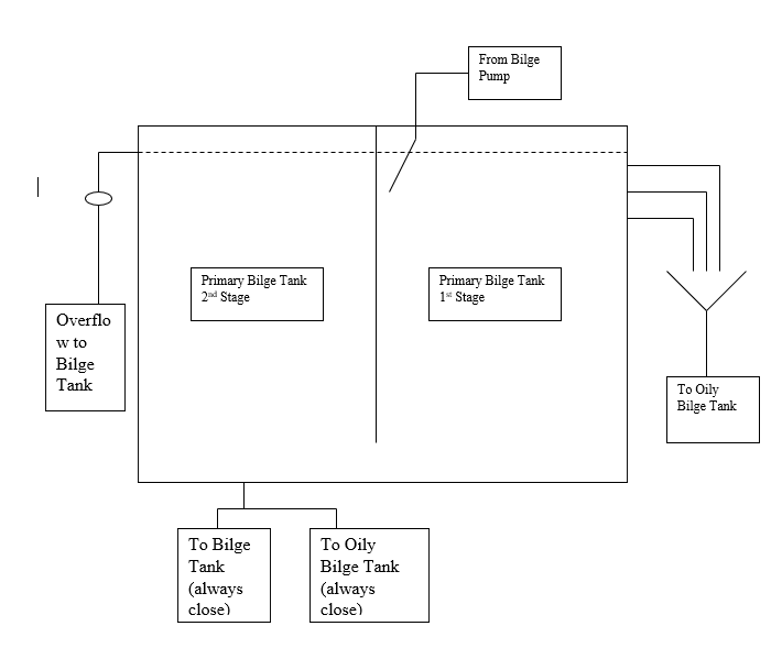
a) Most vessels in the fleet are fitted with a Primary bilge tank of standard arrangement as per below drawing.
b) The standard arrangement of the primary bilge tank consists of a tank with a center partition dividing the tank into 1st stage and 2nd stage. The 2 stages are connected at the bottom of the tank.
c) The 1st stage has the inlet of oily water from the bilge pump, and 2 or 3 test cocks fitted at different levels.
d) The 2nd stage has an overflow pipe with no valves and leading to the bilge tank. This may have a sight glass.
e) Drain valves are fitted at the bottom of the tank. These may be in the 1st and/or 2nd stage, with a choice of leading to the bilge tank or oily bilge tank.
f) Normal operation of the primary bilge tank should be as follows:
- (i)Thoroughly clean the empty tank and close all drain valves. Under normal operation the drain valves should never be opened, hence it is advisable to lash close these valves.
- (ii)Fill up the tank with clean water up to the overflow pipe level.
- (iii)The primary bilge tank is now ready for use and oily water from the bilge wells can be pumped into the 1st stage. An equal amount of clean water will then overflow into the bilge tank. Please note that the primary bilge tank acts only like a transit tank where inlet = outlet.
- (iv) Oil if any, in the inlet water will collect in the 1st stage, and slowly the oil quantity in the 1st stage will increase. Note DO NOT drain any water from the tank and always maintain level at overflow mark. Mud and heavy sediments will settle at the bottom and thus will not be carried to the bilge tank. Opening the drain valves will result in the sediments passing to the bilge or oily bilge tank, which is not desirable.
- (v) During operations, check oil level by slowly opening the 2nd from top test cock. If traces of oil are found it means that oil level has reached this cock. Then close this test cock and open the upper test cock. This will drain out the oil at the top and the oil water interface will move up. When traces of water start to come from the upper test cock, or there is no flow, shut the cock. Note again DO NOT open bottom drain valves and do not lower level in the tank.
g) The same procedure from 3 to 5 is to be used every time during internal transfer of bilge water. This way the 2nd stage should have almost pure water and thus the bilge tank will also have only water with no oil. Also, the mud and sediments will remain in the Primary bilge tank and will not be carried over to the bilge tank, and from there to the OWS.
h) Please remember - never lower the level in the primary bilge tank by opening the drain valves. These are to be used only for maintenance or cleaning, which should not be frequent.
i) If used properly the oil and sediments in the bilge system will be restricted to the Primary Bilge Tank. The Bilge Tank will be free of oil or muddy sediment and OWS operation should be much easier with less frequent alarms and require lesser cleaning/changes of filters and the coalescer.
j) Frequent cleaning of the Primary bilge tank is not necessary and should be avoided. The sediment should be allowed to accumulate at the bottom of the tank and the excess oil removed as described above. Some oil may remain at the top of the 1st stage and this does not pose a problem. Depending on the condition of the Primary bilge tank, cleaning can be considered once in 4 to 6 months. If the tank is clean, the interval can be more than 6 months.
k) For cleaning, first try to remove as much of the oil as possible. Use oil absorbent pads or old newspapers to remove the floating oil. Then try to decant the water without disturbing the sediment. Finally clean the sediment (mud) with cloth and incinerate the cloth. This way the mud and oil does not re-enter the bilge system.
Caution:
- It should be noted that these procedures and guidelines are for vessels fitted with the standard Primary Bilge Tank of the design as show in the drawing.
- Vessels fitted with a primary bilge tank of any other design or those not fitted with a primary bilge tank should consult the Tech. PIC for guidance.
l) Standard Arrangement of Primary Bilge Tank
4.6.2.5 Engine Room Sludge Treatment Procedure
The sequence of Sludge Treatment shall consist of but not limited to the following daily works; (Basic Sequence):
a) The sludge from the Purifiers shall be collected to the Sludge Tank.
b) The sludge in the Sludge Tank shall be transferred by the Sludge Pump to Waste Oil Settling. Tank. The Drain Valve of the Sludge Tank shall be always kept closed.
c) The sludge tank outlet valve shall always be kept in closed position except during transfer operation time. This is to ensure that the sludge tank high-level alarm is received at the time of purifier leakage and corrective action is taken. This eliminates the possibility of Waste Oil Tank or Bilge Sludge Oil Tank (Bilge Oil Tank, Oily Bilge Tank) getting filled accidentally up when the purifier leaks.
d) The Waste Oil Tank or Bilge Sludge Oil Tank (Bilge Oil Tank, Oily Bilge Tank) shall be transferred to the Waste Oil Settling. Tank and water shall be separated and drained to the Bilge Tank (Bilge Storage Tank) or Waste Oil Tank / Bilge Sludge Oil Tank (Bilge Oil Tank, Oily Bilge Tank).
e) The Waste Oil Settling. Tank shall be heated sufficiently (to evaporate mixture water) and after settling, the water shall be drained to Bilge Tank (Bilge Storage Tank) or the Waste Oil Tank / Bilge Sludge Oil Tank (Bilge Oil Tank, Oily Bilge Tank) depending on the pipeline.
f) The Incinerator shall be used to burn off the oil from the Waste Oil Service. Tank (Waste Oil Settling. tank).
g) The Stuffing Box Drain Tank shall be shifted to Waste Oil Settling. Tank / Waste Oil Service. Tank (FO Waste Oil tank, Slush tank, and Sludge Settling tank) as applicable for burning the oil.
h) The Chief engineer shall ensure that the Incineration is carried out only when E/room is attended.
i) In case of short Voyages where Incineration is limited and Waste Oil Tank or Bilge Sludge Oil Tank (Bilge Oil Tank, Oily Bilge Tank) is filled up the transfer to Shore Reception Facility shall be considered. However, it shall be borne in mind the availability of this facility at the port and cost effectiveness of the operation. The Company shall be informed, and permission taken before Shore reception facility transfer option is considered. Record of such disposal shall also be recorded as per GMP.
4.6.2.6 Locking of Bilge O/B Valve and Control of Key Exchange
The procedure for locking the Bilge Overboard valve and controlling key exchange is as follows:
a) The Bilge Overboard valve in the Engine Room shall be locked with a Mechanical Linkage Mechanism using two independent padlocks, except when in use. One full set of keys for the padlocks shall be with the Master, and the other set shall be with the Chief Engineer to ensure the Master is always aware of the overboard transfer. Each padlock has 3 keys, but only one key per lock is required for operation. The extra 2 keys of each padlock (total 4 keys) shall be clearly marked for identification and kept in the Master’s safe.
b) The inventory of Bilge Overboard locks (three keys for each padlock, totaling six keys) must be handed over to the incoming Master and documented in the Master’s handover form.
c) The special feature of this lock is that once the lock is opened, the key cannot be removed from the lock. This ensures that the Master can confirm that once the keys are with him, the lock and Bilge Overboard valve are positively secured. A physical check of the lock and securing arrangement shall be carried out by the Master periodically.
d) The Master and the duty officer shall be informed before the OWS Bilge transfer. The Master’s key for securing the Bilge Overboard valve shall be delivered to the Chief Engineer if the Master approves discharging the OWS Bilge transfer.
e) The Master shall then record the time of handing over the key in the Deck Log Book. The Chief Engineer will also record the time of receiving the key in the Engine Log Book.
f) When the discharge through OWS has commenced, the Master and the duty officer shall be informed. The Master shall monitor the operation of discharging through OWS for a while from the outset of the operation.
g) The Master and the duty officer shall be informed after the OWS Bilge transfer, and the Bilge Overboard valve shall be secured again. One of its keys shall be returned to the Master.
h) Upon receiving the key, both the Master and the Chief Engineer shall record this time in the Deck and Engine Log Books, respectively.
4.6.2.7 Sealing Waste Stream Discharge Pipeline
The procedure for sealing the waste stream discharge pipeline is as follows:
a) Pipelines, valves, and flanges that are susceptible to tampering or unauthorized dismantling with the intention to bypass the OWS or authorized methods of Engine Room (E/R) waste disposal shall be sealed with company-supplied special seals. These seals will have the company logo, serial number, and sealing wire. Details of such seals shall be maintained in the Seal Register as per E81 Register of Bilge Pipeline Seals.
b) If, due to maintenance or emergency purposes, the seals need to be removed, prior information must be obtained from the vessel manager or the GM of the technical group.
c) Two sets of the vessel’s Bilge Piping Diagram, with marked areas to be sealed and secured, are issued onboard the vessel. One copy is always maintained with the Master, and the Company keeps one copy of this diagram for reference.
d) The Master shall always retain the spare numbered seals in his personal possession and shall never hand them over to the Chief Engineer.
e) Upon removal and re-installation of a seal by the Master, the office shall be informed, and a record of the seal change shall be made as per E81 Sealing Activity. During the vessel manager’s subsequent visit, the seal serial number shall be verified.
f) The details of the sealing arrangement are explained below:
g) Prepare the Bilge Piping Diagram for each vessel and distribute the seal point numbers to pipes and valves between the Bilge Pump Outlet and Bilge Overboard Valve in the following order:
- Shore Connections (Port and Starboard)
- Bilge Pump (Outlet and Flow Adjust Valve) to OWS
- Pipes after OWS
- 3-Way Valve and Sight Glass to Bilge Tank
- After the 3-Way Valve to the Overboard Valve
- Direct Bilge Suction and Emergency Bilge Suction
h) The details of the sealing arrangement and the regular checks of the sealing conditions shall be conducted by the Chief Engineer, as mentioned in the E81.
4.6.2.8 Bilge Water Equipment Maintenance
a) Bilge water equipment shall be maintained and tested in accordance with vessel-specific PMS.
b) Emergency Bilge Suction Valve shall be operated every 3 months and tested. The seal is to be broken and the valve resealed after testing. A task shall be created in PMS for this testing.
c) The Chief Engineer shall verify that bilge water equipment is maintained as per the PMS. When such equipment, including any alarm printers and recorders, is installed, modified, or serviced, it shall be recorded in the PMS. He shall confirm that required spare parts are kept on board.
d) The Chief Engineer shall be notified immediately of any equipment failure in the bilge water processing system. The Master shall notify the vessel manager and the GM of the technical group of any equipment failures that affect the ability of the vessel to process bilge water.
e) The vessel shall always maintain one spare OWS Coalescer element on board.
4.6.2.9 Oily Content Meter Servicing
Calibration of OCM shall be carried out as per manufacturer’s recommendation. The Chief Engineer shall ensure that a record of such test is made in the PMS.
4.6.2.10 Equipment with Oil to Sea Interfaces
The vessel is required to identify and monitor all systems having oil to sea interfaces. These systems include stern tubes, bow thrusters, and any similar systems that utilize oil reservoirs or oil header tanks. Such systems shall be closely monitored.
4.6.2.11 Disposal of Bunker Samples and the Small Quantity of Lube Oil
a) Bunker samples shall be retained under the ship’s control until the fuel oil is substantially consumed, but in any case, for a period of not less than 12 months from the time of delivery.
b) Bunker samples shall be disposed of in the engine room Sludge Tank. An entry shall be made in the Oil Record Book Part 1 under Code “I” giving details about such disposal, including the place of bunker, date, seal no. of sample bottles, and any other details if available.
c) Small quantities of lube oils, about 10 to 30 litres generated in the engine room during routine maintenance, shall be disposed of in the engine room Sludge Tank. A simple entry shall be made in the Oil Record Book Part 1 under Code “I”.
4.6.2.12 Oil Pollution Prevention Measures in Polar Waters
a) Operational Requirements
- (i) In Arctic waters, any discharge into the sea of oil or oily mixtures from any ship shall be prohibited.
- (ii) The provisions of paragraph 1) shall not apply to the discharge of clean or segregated ballast.
- (iii) Subject to the approval of the Administration, a Category A ship constructed before 1 January 2017 that cannot comply with paragraph 1) for oil or oily mixtures from machinery spaces and is operating continuously in Arctic waters for more than 30 days shall comply with paragraph 1) not later than the first intermediate or renewal survey, whichever comes first, one year after 1 January 2017. Until that date, such ships shall comply with the discharge requirements, regulation 15.3 of MARPOL Annex I.
- (iv) Operation in polar waters shall be taken into account, as appropriate, in the Oil Record Books, manuals, and the shipboard oil pollution emergency plan or the shipboard marine pollution emergency plan as required by MARPOL Annex I.
b) Structural Requirements
- (i) For Category A and B ships* constructed on or after 1 January 2017 with an aggregate oil fuel capacity of less than 600 m3, all oil fuel tanks shall be separated from the outer shell by a distance of not less than 0.76 m. This provision does not apply to small oil fuel tanks with a maximum individual capacity not greater than 30 m3.
- (ii) For category A and B ships* other than oil tankers constructed on or after 1 January 2017, all cargo tanks constructed and utilized to carry oil shall be separated from the outer shell by a distance of not less than 0.76 m.
- (iii) For category A and B ships* constructed on or after 1 January 2017, all oil residue (sludge) tanks and oily bilge water holding tanks shall be separated from the outer shell by a distance of not less than 0.76 m. This provision does not apply to small tanks with a maximum individual capacity not greater than 30 m3.
Note:
- *Category A ship means a ship designed for operation in polar waters in at least medium first-year ice, which may include old ice inclusions.
- *Category B ship means a ship not included in category A, designed for operation in polar waters in at least thin first-year ice, which may include old ice inclusions.
4.6.2.13 Related Forms and Records
- EMS-14 Daily Report of Bilge and Sludge Data
- E81 Register of Bilge Pipeline Seals
- Daily Tank Condition Record